

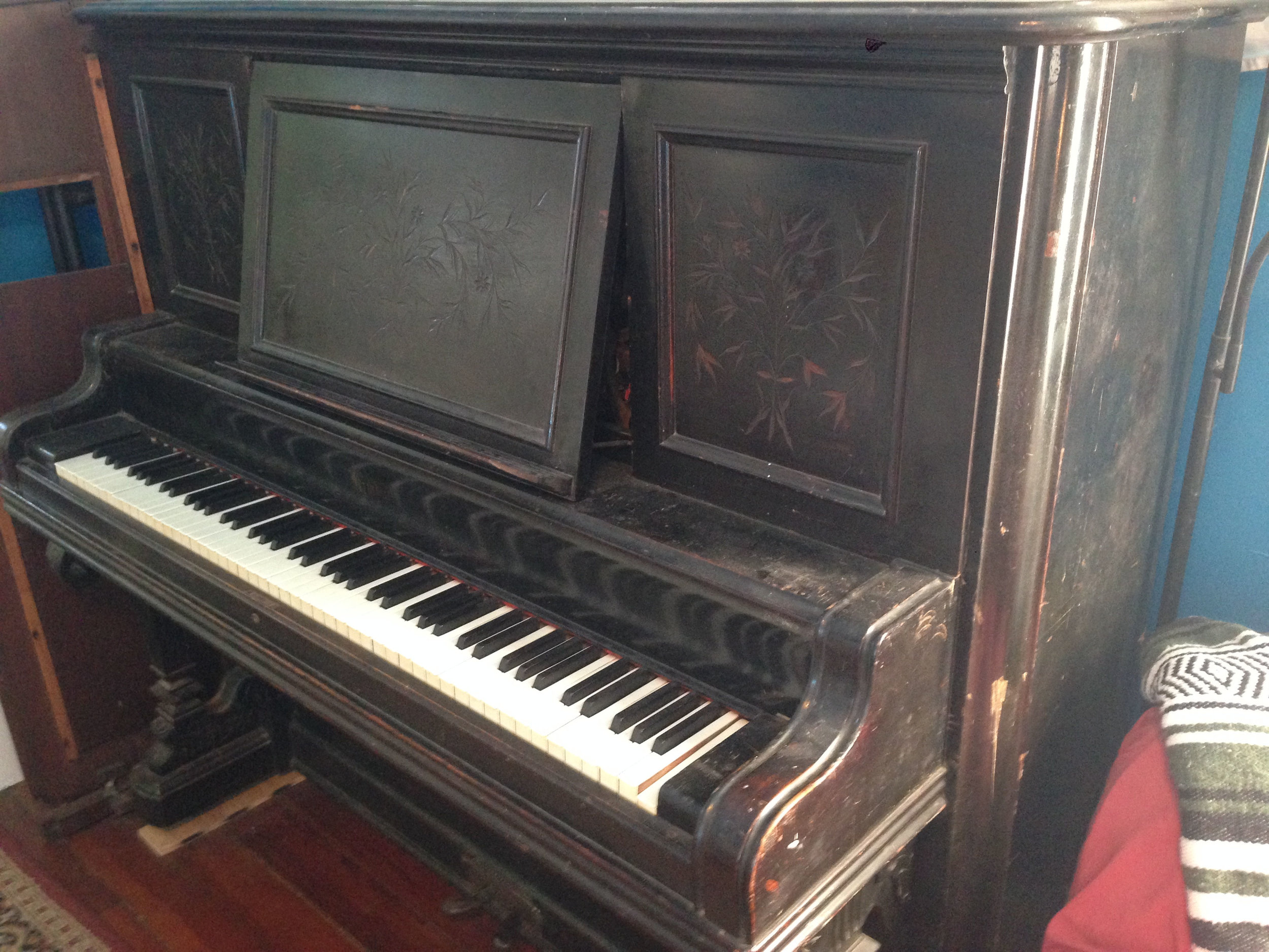
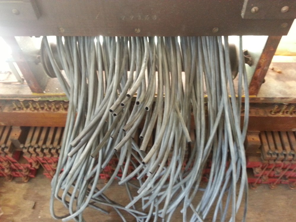
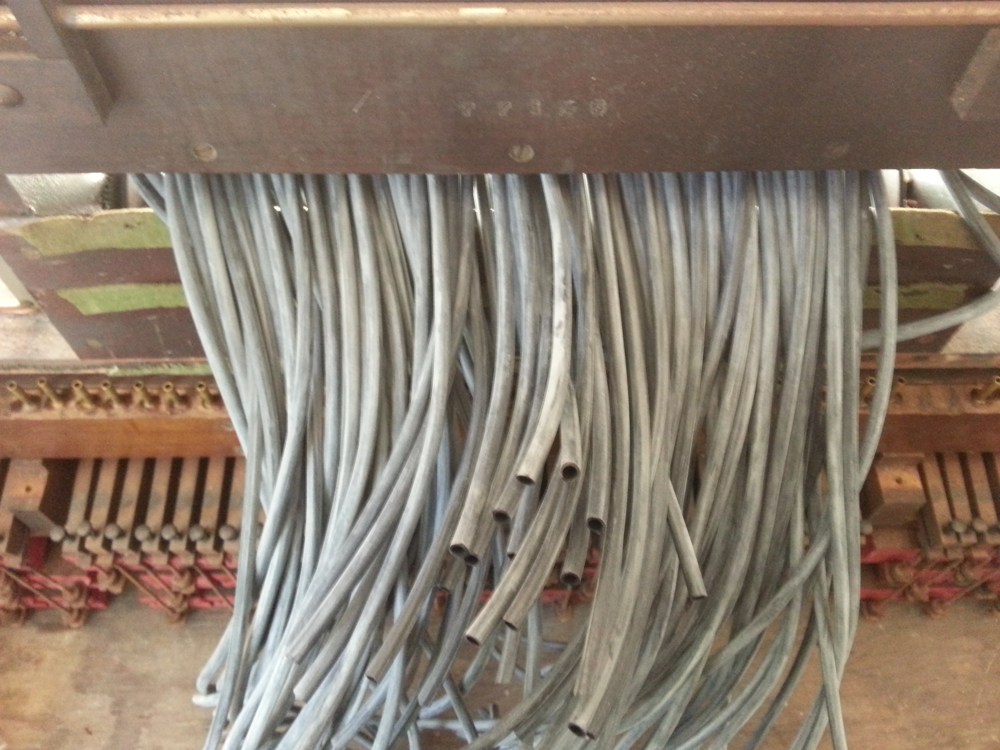
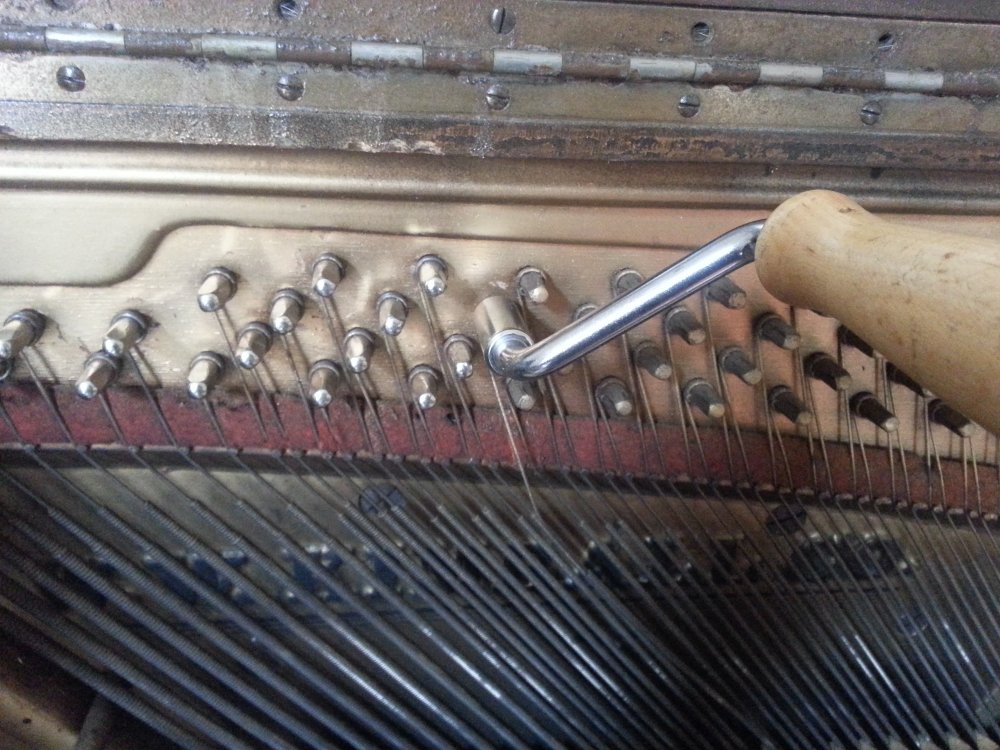
A problem that I occasionally find in older pianos is that of expanded key-leads.

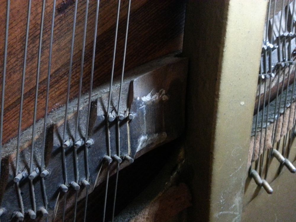
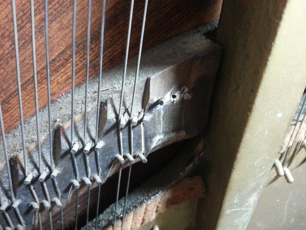
These expanded key leads are causing the keys to bind against each other. This issue was caused by rodents living in the piano, as is evident by the teeth marks on the keys.
If you look at a piano action, you will notice that the hammers at the bass end are much larger (and therefore heavier) than the hammers at the treble end. The heavier bass hammers take more force to push toward the strings than the lighter treble hammers.
In order to create a consistent amount of pressure needed to play the keys across the keyboard, lead weights are pressed into the sides of the keys. Keys that push heavier hammers have more weight pressed into them than keys that push lighter hammers. The lightest hammers at the far right end of the keyboard have no weight added at all.
If moisture or an acidic environment is introduced into the keyboard, it will cause the lead to oxidize and expand. Some technicians claim that keys that are made from basswood naturally create a slightly acidic environment. This means that the best way to avoid this with a basswood keyboard is to aerate the keys by leaving the fallboard open at all times. Other ways that key leads can oxidize is if water is spilled into the keyboard, if the piano lives in a very humid environment, or if rodents live in the piano and are urinating on the keys. Usually, you can get an idea about what the cause is by looking to see where the oxidized leads are located. If the whole keyboard has expanded leads throughout, it is likely the cause of high humidity or unventilated basswood keys. If the oxidation is concentrated in small areas, there was likely a liquid spilled on the keyboard or mice living in the piano.
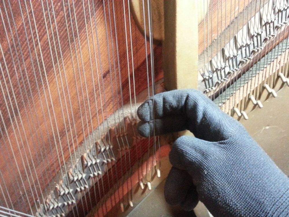
A little bit of oxidation of the key leads wont hurt anything, but eventually the leads can expand so much that they will rub on neighboring keys. This will cause friction and result in sluggish or binding keys. When this happens, they key leads need to be trimmed so that they are once again flush with the side of the key. Be careful when undertaking this process, as lead dust is toxic if inhaled. Wear a respirator and gloves, and have a vacuum with a HEPA filter handy to clean up the dust during the process.
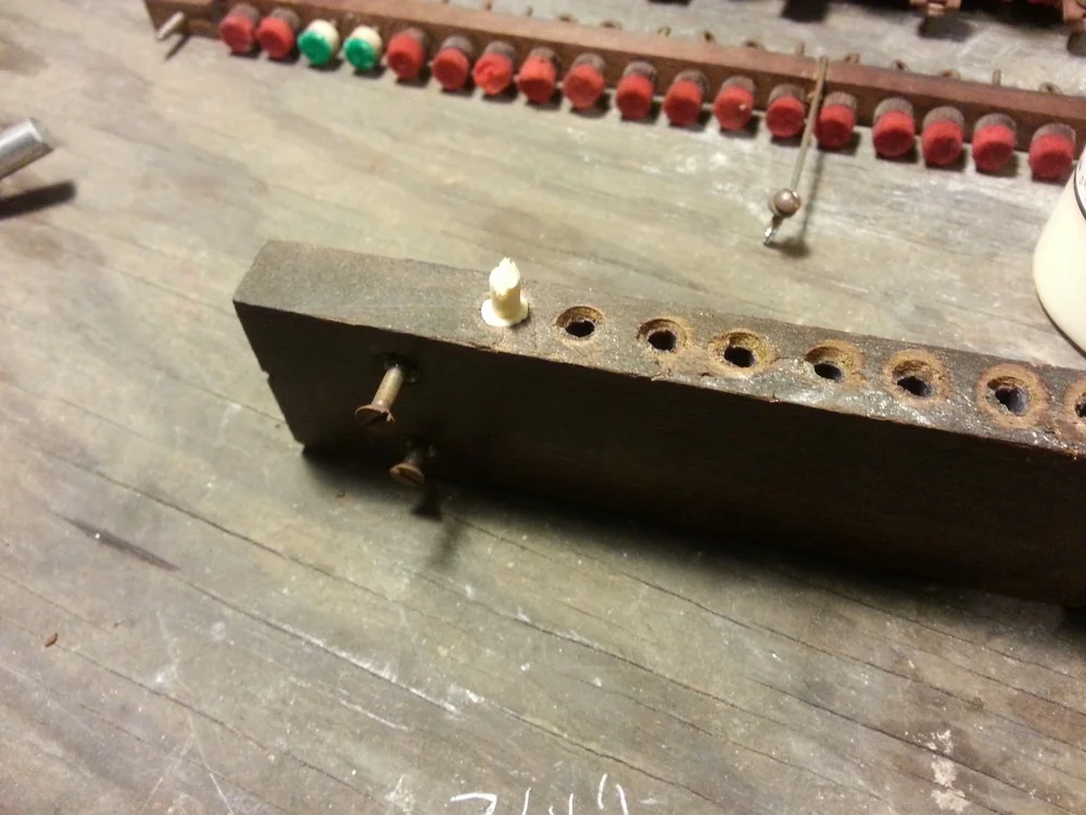
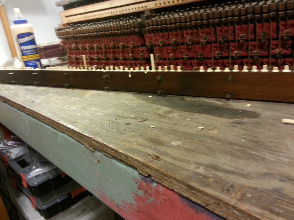
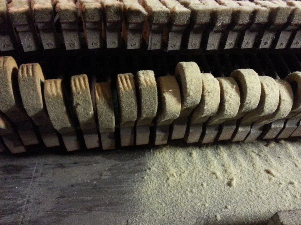
The first step is to remove all of the offending keys from the keybed.
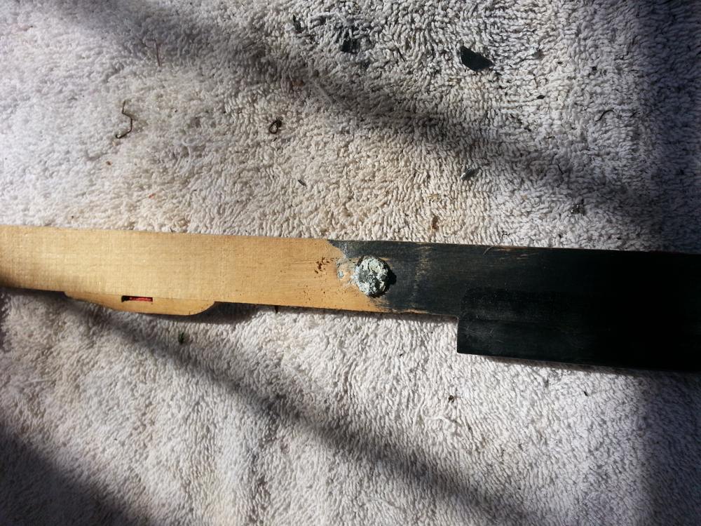
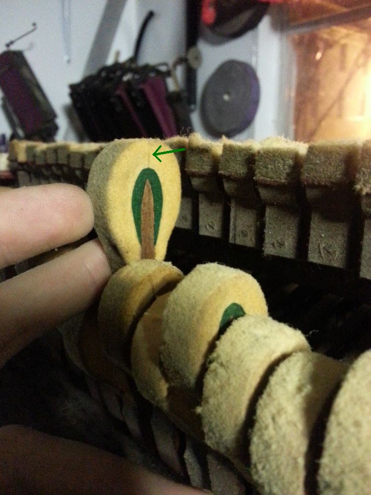
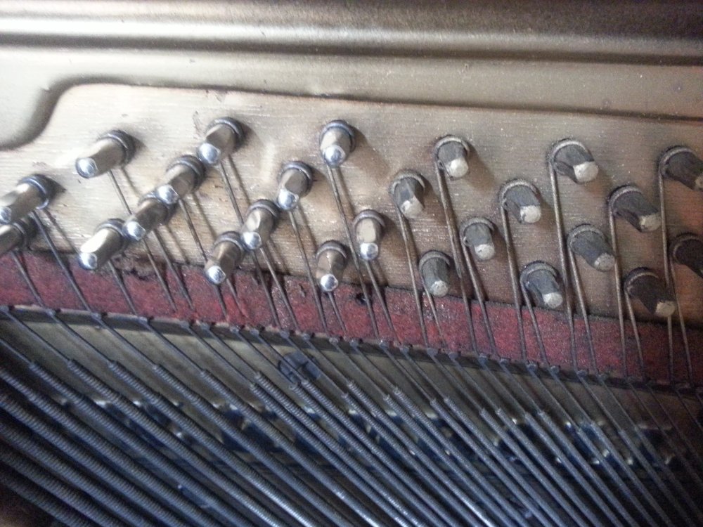
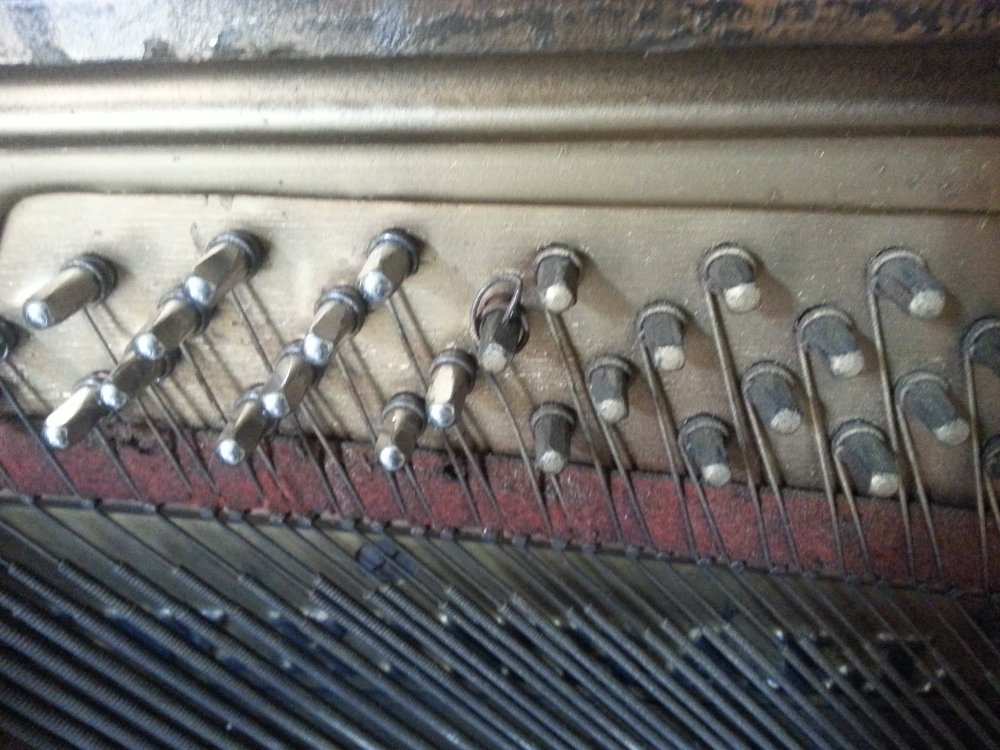
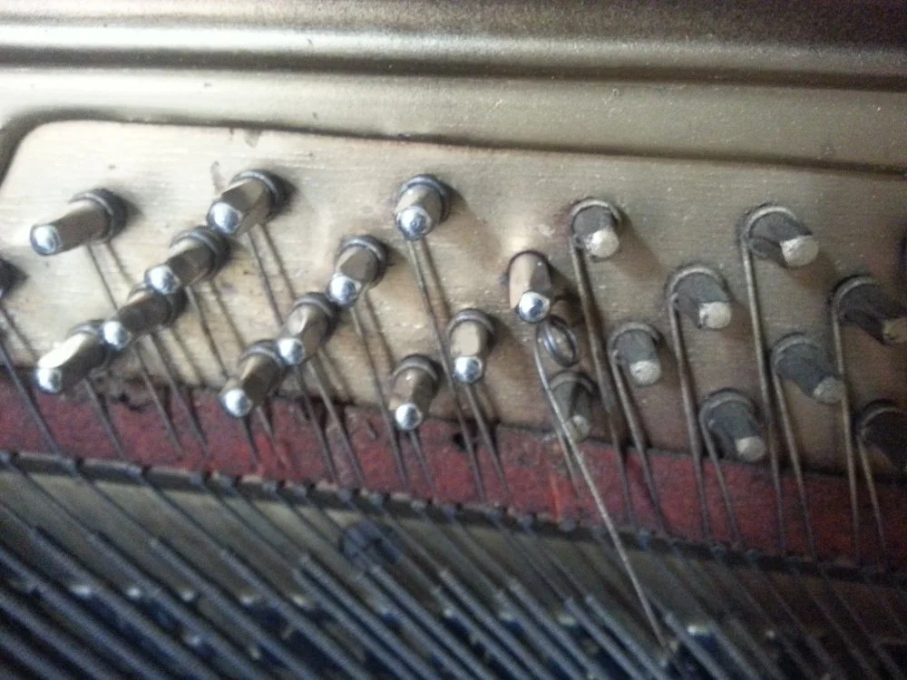
An expanded key-lead.
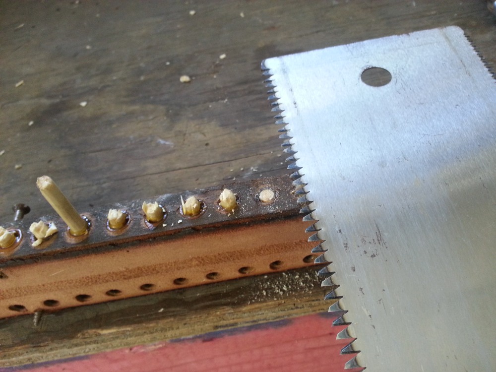
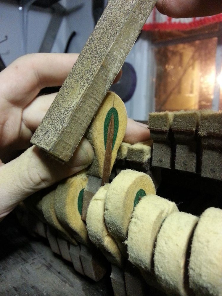
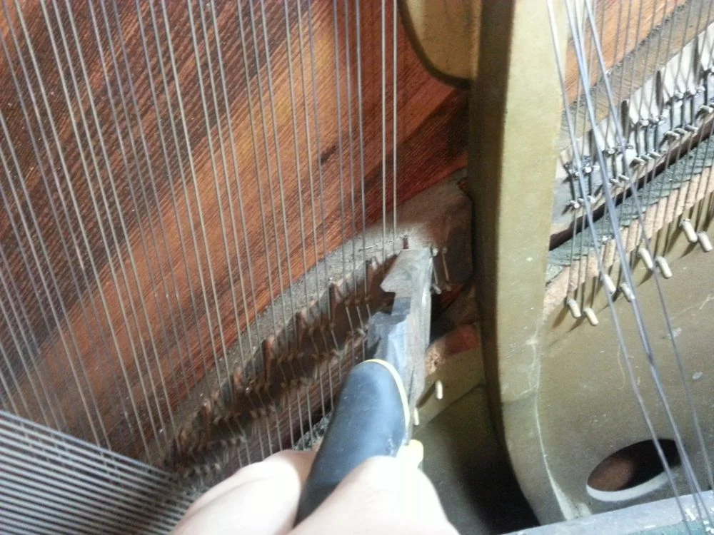
Set them down on a rag and vacuum up any lead dust that is left on the keybed. Using a sharp chisel, slice through the expanded key-lead so that it is flush with the side of the key.

Make sure your chisel is sharp before cutting into the key-lead.
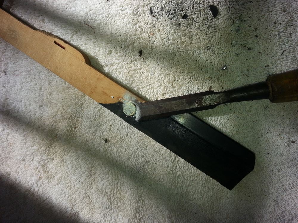
Pushing the chisel through the key-lead.
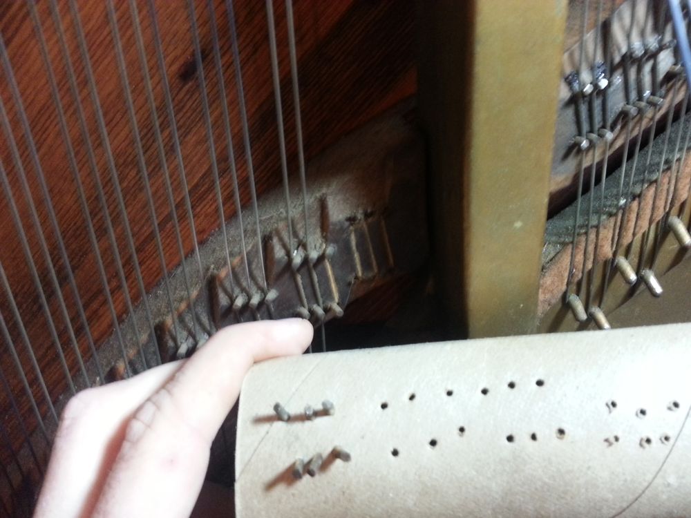
The goal is to create as little dust as possible, so avoid using a file or sandpaper. Go down the line of keys, slicing through the expanded leads on each side, and vacuuming up the dust and lead scraps.

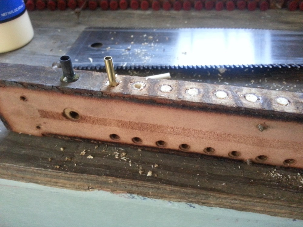
The trimmed key-lead.
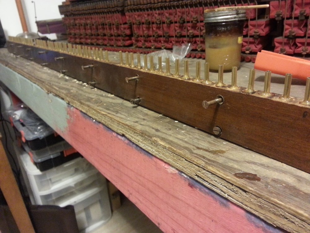
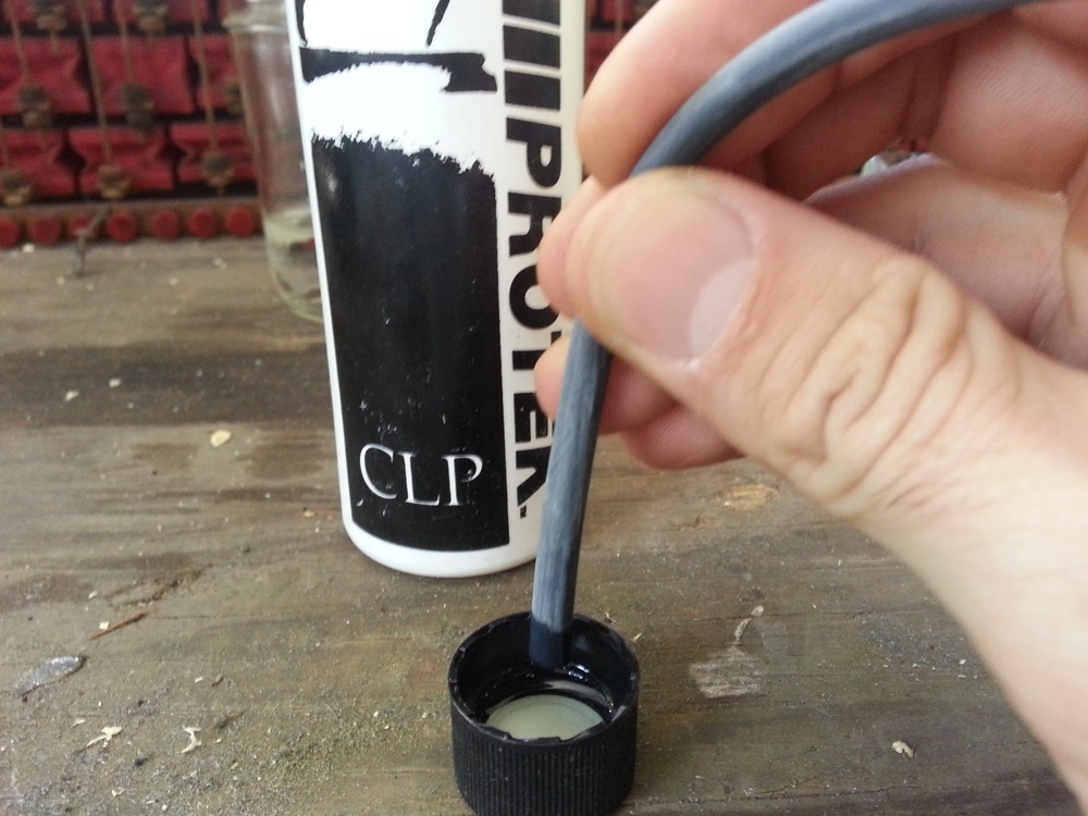
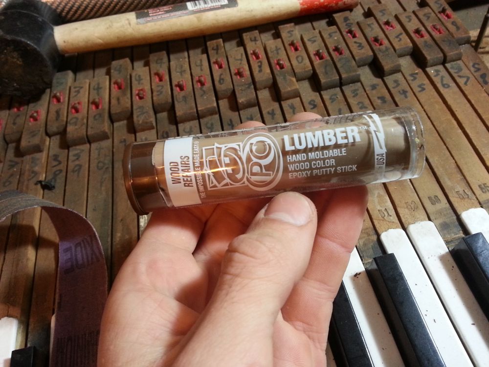
After trimming the leads, I like to brush some lacquer or shellac over the exposed sides of the leads to prevent further oxidation.
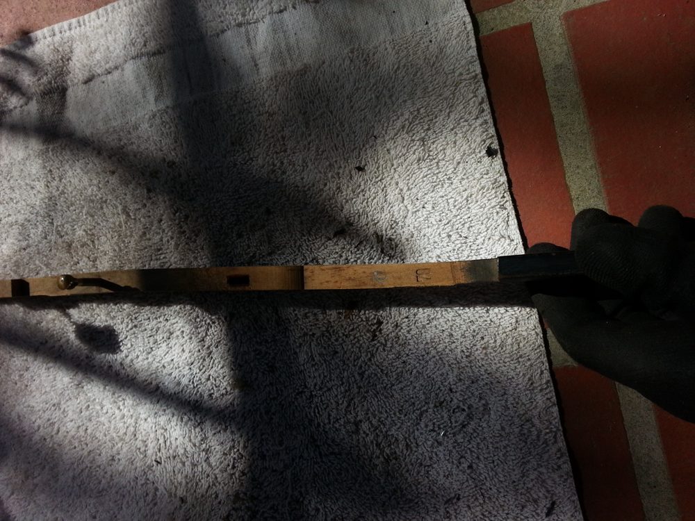
Both sides of the key-lead have been trimmed flush with the key.
Replace the keys and test them to make sure they all move smoothly. Finally, vacuum up any lead dust that fell onto the rag.
Recent Blog Posts


I have been servicing and tuning pianos in NOLA since 2012 after first becoming interested in piano technology in 2009. With a background in teaching bicycle mechanics, I bring a methodical mindset and a love of sharing knowledge and skills to the rich musical culture of New Orleans.